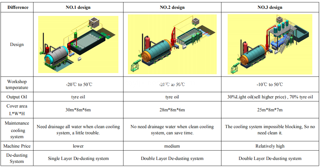
Waste Tyre Pyrolysis Machine made by Yilong have 3 designs can be chosen by customer, and 3 designs have been widely used in China and other countries. We have got more than 1000 customers using our Pyrolysis Machine. And we have CE/ISO/SGS certificate for validating our company honor. We deserve your trust.
Welcome your visit anytime to learn detailed difference and visit our running machine.
Waste Tyre Pyrolysis Machine Waste Tyre Pyrolysis Machine,Pyrolysis Machine,Automatic Waste Tyre Pyrolysis Machine,Waste Tyre Pyrolysis Processing Machine Shangqiu Yilong Machinery Equipment Co., Ltd. , http://www.pyrolysis-equipment.com
Speed ​​Sensor Installation Instructions In general, linear switches can be used for the switches that can see the linear motion. There are no switches with a part of linear motion exposed, and angular speed sensors can be used.
When mounting the sensor, try to install the sensor in the moving mechanism closest to the moving contact so as to avoid gaps or non-linearities in the intermediate switching part that affect the test accuracy. The linear sensor has the highest speed and stroke accuracy and is the most reliable. It is recommended to use linear sensors as much as possible.
1. The linear sensor installation is equipped with a linear sensor with a length of 50mm and 300mm, respectively. The 50mm linear sensor is mainly used for vacuum switch stroke and speed testing, testing stroke <40mm; 300mm linear sensor is mainly used for SF6 stroke and speed test, test stroke <280mm. For the 110kV, 220kV low oil switch test, it is inconvenient to directly mount on the moving contact due to the long stroke, and can only be measured indirectly on the transmission rod. 2. Angular velocity sensor installation The angular velocity sensor is divided into an angular velocity resistive sensor and an angular velocity encoding sensor. The angular velocity resistive sensor is a high-precision potentiometer, and the angular velocity encoder uses a grating principle. The angular velocity sensor directly tests the relationship between the rotation angle and the time, and then automatically calculates the proportional coefficient according to the input reference distance or the total stroke, and finally converts into the actual speed and stroke.
2. Control Line Wiring Description This tester can output the DC power needed for high-voltage switch-on and switch-off, and can perform three different control methods of internal synchronization, external synchronization and empty node of the switch test.
(1) During the field test of the internal synchronization test, if the internal power supply of the instrument is used, the internal synchronization method and rated voltage are set according to the test coil voltage, and the closing control line (red), the opening control line (green), and the public line ( Black) Connect to the corresponding position of the switch and connect the other end to the "Internal Sync" port (Aviation Plug) on ​​the instrument panel.
Pay attention to cut off the high-voltage switchgear's own operating power (disconnect the knife or pull out the insurance) when wiring, so as to avoid two kinds of power conflict.
(2) During the field test of the external synchronous test wiring, if the external power supply of the instrument is used, the “external synchronization†mode shall be selected to connect the closing control line (red), the opening control line (green), and the public line (black). Go to the corresponding position of the switch and connect the other end to the “out-of-sync†port on the instrument panel (air plug).
(3) Passive contact synchronous test When wiring the field test, if the tested high-voltage switch's own sub-switching and closing power supply is used, the “empty contact†method shall be selected, the closing control line (red) and the sub-gate control line (Green), public line (black) is connected to the corresponding position of the switch, and the other end is connected to the “empty node†port (air plug) of the instrument panel. The instrument provides 2 independent passive air contacts. High voltage switch dynamic characteristics tester.

High-voltage switch tester sensor installation instructions
High-voltage circuit breakers are one of the most important control devices in the power system. The number of high-voltage circuit breakers in the power grid is the largest, and the operating conditions and technical requirements are relatively complex. The operational reliability of the high-voltage circuit breaker is not only related to the high-voltage circuit breaker itself, but also affects other equipment and even the entire power grid. Therefore, testing the dynamic characteristics of high-voltage circuit breakers is a very important task. However, the traditional method of testing the dynamic characteristics of high-voltage circuit breakers has the disadvantages of complicated operation and low test accuracy. In order to solve these problems, we have developed BOKC-6B high voltage switch dynamic characteristics tester.